
In the past, designers and engineers used separate software tools for design analysis and design documentation. Calculate in one platform and document the answer in another. Think Excel, Trace 700, or AGI 32 and AutoCAD. This approach was time-consuming and error prone as it required transferring data between different software tools. Let’s be honest, it still beat doing it all by hand. The evolution from separate design documentation software and design analysis software to an integrated design analysis and documentation workflow has been driven by the need to improve the efficiency and accuracy of the design process.
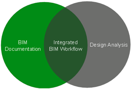
To address these challenges, software companies have increasingly focused on integrating different stages of the design process into a single, unified platform, namely Building Information Modeling (BIM). This integrated approach allows designers to model, analyze, and document their designs in a single environment, reducing the time and effort required to move between different software tools while also improving the quality and accuracy of the final design. The goal is to move these two circles close together until we hit the idealized integrated BIM workflow. That does not necessarily mean a single software package. It just means that the future software packages have more interoperability than the ability to move data between them. Think of connected databases instead of a copy of one.,
BIM to HVAC Load Modeling
The design and construction of buildings involves a complex process that requires a wide range of engineering expertise. One of the key components of building design is the heating, ventilation, and air conditioning (HVAC) system, which is responsible for ensuring good Indoor Air Quality (IAQ). Accurate HVAC load modeling is crucial to the design of an efficient and effective HVAC system.
BIM and HVAC load modeling are two related, but distinct processes used in building design and construction. BIM is a digital representation of a building’s physical and functional characteristics. It includes all the information about a building, including its dimensions, materials, and systems. BIM allows architects, engineers, and construction professionals to collaborate and visualize a building’s design and construction process. On the other hand, HVAC load modeling involves calculating the heating and cooling loads required to maintain indoor temperature and humidity levels within a building. This process considers numerous factors, such as the size and orientation of the building, the materials used in its construction, the climate of the area, equipment in the space, and the number of occupants and their activities.
Ideally, the transition from BIM to HVAC load modeling involves using the information generated by BIM to create an energy model of the building. HVAC load modeling uses geometric information from BIM to create a 3D model of the building, and the data about the building’s components and systems to calculate the load of the spaces. The transition sounds simple. However, simple does not mean easy. Autodesk markets that this functionality exists in their BIM product Revit.
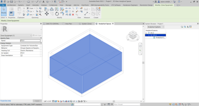
In previous versions of Revit, designers used the Heating and Cooling Loads function to determine the heating and cooling requirements for a building. However, starting with Revit 2022, Autodesk introduced a new Systems Analysis feature which creates analytical surfaces and analytical spaces in the model. These are actual elements that can be scheduled and isolated in views with visibility graphics. Systems Analysis also moved to the what-you-see-is-what-you-get (WYSIWYG) method for those objects. This made the gbXML outputs match the elements on the screen, adding transparency to the process. Not only are you able to export the elements, but Autodesk also says that Revit can calculate those objects without leaving the software. Is this the idealized integrated BIM workflow that we have been working toward?
While there are a variety of software tools available for HVAC load modeling, many design professionals would not consider Revit to be the most effective choice. Revit is an architectural and building systems design software that is widely used in the construction industry. It can be used to create building models with HVAC systems. However, it is not specifically designed for HVAC load modeling.
Issues With Load Calculations in Revit
There are several reasons why Revit may not be the best choice for HVAC load modeling. First, while Revit includes some basic load calculation tools, they are not as comprehensive or accurate as those found in specialized HVAC load modeling software. HVAC load modeling software is designed specifically for this task and can consider a wider range of factors, including outdoor weather conditions, building orientation, thermal properties of building materials, and more. While Revit has some of this capability, it is missing critical features. The following is a list of specific issues.
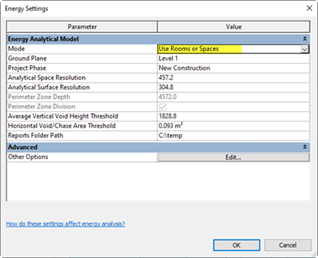
Energy Analytical Model Mode Setting
Internal gains only show the load on the report when “Use Building Elements“ is used and not “Use Rooms and Spaces.” Spaces and analytical spaces both calculate the load, but the values are not transferred to loads report. This was reported to Autodesk and we were lucky enough to get our very own incident ID.
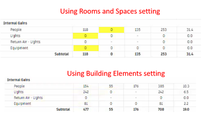
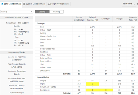
Internal Gains Loads Missing
Delayed Sensible load and Latent Equipment load are not accounted for. The Latent Equipment load is most important. This is a requirement of ASHRAE Standard 183-2007 (RA 2020) section 8.2. Delayed sensible load is not an input in the energy+ engine. The delayed component is a consequence of a radiant factor associated with a load. That radiant factor must bounce around the room until it heats up a surface. Depending on the mass and properties of that surface, it may take a while for that radiation to translate itself into surface temperature and heat up the air in the space. The calculation does not result in either of these loads accounted for in the final total. Section 8.2 of 183 requires that ‘sensible and latent heat gain components of all internal gain contributors shall be considered separately.’
ASHRAE Standard 183 is required by the various codes (2018 IMC Section 312, 2018 IECC Section C403, ASHRAE 90.1-2019 Section 6.4.2 are examples) that we are required to follow for our design. Without this feature, we simply cannot use Revit to do an official calculation.
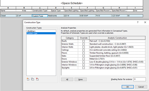
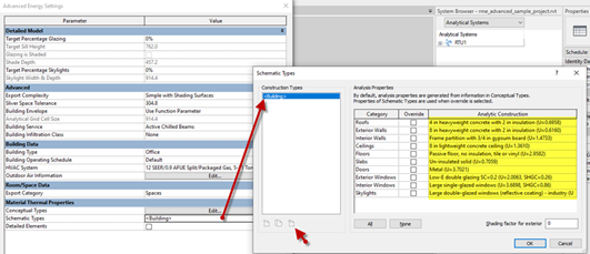
Analytical Construction Overrides
There is functionality to add custom construction types. The construction types can be assigned to the spaces but then don’t transfer to the analytical spaces. The analytical space defaults to Building. There is only one analytical construction definition per category for the analytical spaces and surfaces. This means that all calcs using the override have one setting (i.e., we get one ceiling U value for the whole project).
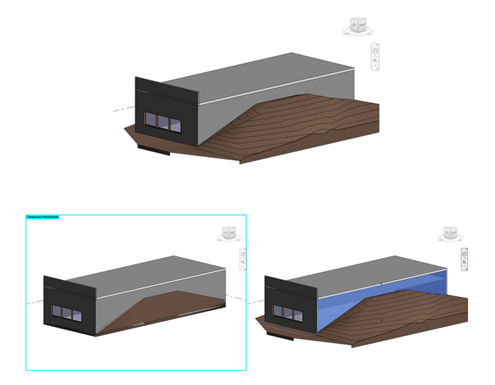
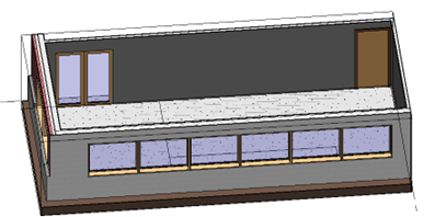
Modeling plenums
Modeling Plenums is difficult. The analytical space workflow will create a plenum object but only if certain conditions are met. If those conditions contradict the needs for other settings, then you must choose between two options for functionality (i.e., choosing between using Building Elements and Use Rooms/Spaces). If plenum objects are not modeled, then the calculation isn’t correct. If the plenum objects are modeled, then there is no way to distinguish between a ducted and non-ducted return plenum. There is no functionality for equipment load either. These factors impact the load and are negligence to ignore.
Multiple construction types of a single space
There’s no ability to modify analytical spaces. It only can come from the automated output. Surfaces are based building objects but are not split for other elements. Example would be grading next to a wall. The wall is the same across the length but the thermal properties over the length are not. What this means for designers is that they can’t define different envelope properties for portions of the same wall. This is something that even the most primitive load software can accommodate.
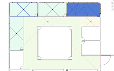
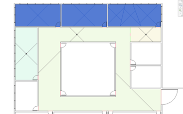
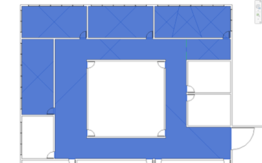
Group by space example
This is especially critical for load calculations so that the peak and block loads can be calculated for each room, zone, and collection of zones served by a single system.
Equipment types don’t match systems
There isn’t a great option for packaged HVAC equipment like an RTU or AHU. We often must pick the closest one, which causes confusion.
Multiple door and window types in a single space
This is only available if the “Use detailed elements” is checked and analytical spaces are created using “Use building elements.” Windows are usually even more impactful to the load than doors. It is imperative that windows with different properties can be independently defined even if they are on a common wall surface.
What are the possible paths forward?
Use Revit Systems Analysis with the architectural elements?
While this is possible, it’s not practical. Most architects are not filling out thermal properties of objects. Additionally, the calculation engine and formula require the thermal properties of individual layers to be correctly modeled. The industry is looking for something that can source data from one location with the ability to modify it after. The mechanical engineer needs to be in control of the inputs to the calculation to certify the outputs.
Use Revit Systems Analysis with the spaces?
This solution is more in line with the preferred workflow. It allows us to control objects that are in our model. However, the control stops short of the space objects. The analytical spaces that are derived from the spaces are not editable. This does not provide the ability to correct anything that is incorrectly automatically generated. Autodesk assumes that since it is automatically generated, it is efficient and correct. If neither of those is true, then you spend an inordinate amount of time correcting Revit to fake out the input feature to get the output you want. This is time wasted fighting Revit instead of calculating the load and engineering the system.
Use the legacy spaces workflow and Heating and Cooling Loads feature?
Ripple publishes an excellent free add-in that drastically increases the speed and clarity of configuring spaces for load calculations by providing features such as an AI-powered ASHRAE 62.1 space type assignment tool. The add-in is intended to be used with the Heating and Cooling Loads tool built into Revit, which was hidden in support of the new Systems Analysis feature (Ripple has documentation on how to unhide this function). Autodesk hiding a feature instead of marking it as deprecated is unusual. Since this is a functionality related to an older feature, investing your workflow into this method might be working on borrowed time. It is possible that Revit will eventually remove the functionality instead of hiding it.
The Heating and Cooling loads tool has many of the same shortcomings as the Systems Analysis tool. There are critical functionalities that are still lacking in Revit itself to do the calculation correctly. A simple example is covered in the Modeling Plenums section above. The Ripple solution gets you close quickly and it’s free, but you are still at the mercy of a rigid input system dictated by Autodesk. How close is close enough? If the software isn’t compliant with ASHRAE 183, then it doesn’t matter how close it is. On some projects, it won’t matter. On some projects, it will matter. How will you be able to know the difference? A well configured Revit can be exported into a gbXML for use in third-party ASHRAE 183 compliant load calculation tools. This gbXML export can be used as a starting point in other tools but is limited as outlined in the sections above.
Use a custom workflow, export to gbXML, scrape e+ data to do the real calc?
There are a handful of other solutions that require us to design and test a software stack workflow that will get the BIM data to a legitimate HVAC load modeling software. Cove.tool is on our radar. Using Ladybug and Pollination Revit plugin to export the model to Rhino using Honeybee JSON (HBJSON) is a possibility. I promise that those aren’t made up words. This requires more time and simply is something that we shouldn’t have to do. This shouldn’t be this complicated.
In conclusion, while Revit can be a useful tool for architectural design and HVAC system modeling, it is not the best choice for HVAC load modeling in our experience. The features are intended to be fast, which they are. Revit will get you a fast and close answer. How close depends on the complexity of your building. If you’re comfortable with close, then you are welcome to use Revit but beware of using it for final load calcs. You may not be complying with ASHRAE 183 and, by consequence, the locally adopted code.
While Revit Systems Analysis is a powerful tool, it is important for designers to be aware of the limitations of the software and to ensure that their HVAC load models are accurate and reliable by validating their results using other methods and sources of data. This functionality in Revit is not new and we struggle to understand why/how such fundamental and critical elements are missing.
Are we really the first ones to bring these items to Autodesk’s attention? In the meantime, we prefer something that is accurate and that we are willing to put our reputation and, most importantly, our seal on. HVAC load modeling is a complex and specialized process that requires detailed calculations and a deep understanding of building physics and thermal dynamics. To ensure accurate and reliable results, it is important for HVAC engineers to use specialized software that is designed specifically for this task. By using the right tools and expertise, HVAC engineers can design HVAC systems that are efficient, effective, and tailored to the specific needs of each building. We look to Autodesk to improve the software to match the needs of the industry and look to the industry to demand that they do so.
The information herein is for general informational purposes and represents the experiences and opinions of the authors. Henderson Engineers, Inc., makes no representations or warranties about, and assumes no legal liability for, the accuracy or completeness of any information herein.

Jared Carlson, engineering director, will be presenting Navigating Change when Introducing New Tools and Processes to Maintain Buy-In and Insure Adoption at the Advancing Design Quality Management Summit. He’s excited to dive into the innovative ...
Read More
Starting May 13th Mark Chrisman and Laura Longoria will be in Orlando for BOMA International’s Medical Real Estate Conference. Team Henderson is excited to explore healthcare real estate from every angle and lean into what ...
Read MoreJoin our email list to get the latest design innovations, technical content, new projects, and research from Henderson’s experts delivered straight to your inbox.