
DfMA (Design for Manufacture and Assembly) doesn’t have to be an exclusive club of certain project types. Building on the concepts of modular construction, DfMA is the next evolution for an automated AEC industry. The BIM process and VDC process need to fit with the overall design process. The final output also needs to meet hard-coded engineering standards. Systems design and sequencing challenges can be overcome with modularization and automation. We’ll show you how. This article makes the concept of DfMA more accessible to different project types. We will walk through the story of identifying levels of DfMA, working with a large contractor to develop design modules, then on through design, fabrication, and installation.
Introduction
We’re going to discuss a couple of different topics in silos, and then show how they all come together in the end. First, we’re going to cover DfMA from an engineering standpoint, and then finish it off with generative design and BIM. These are not new concepts but we feel that they are underutilized in the building systems design area of the AEC industry.
Identify Applications of Different Levels of DfMA Approaches
One important concept is the way we talk about DfMA in the AEC industry. We often see DfMA used interchangeably with terms like modular construction, prefabrication, and off-site construction. Really, that’s not the best representation of DfMA. A better statement is that DfMA produces components in support of these construction principles in an effort to make them more effective.
Why Scale Matters
Another important concept is scale. Take the two Yodas pictured below. The one on the left has a module scale (size of the Lego brick) that is really close to the overall scale of that Yoda figurine. The one on the right has a module scale that’s quite a bit smaller in relation to the overall scale of the model and you’re able to see more detail.

Engineering design principles follow similarly: as the scale of the module gets smaller in relation to the building, you can get more definition with your designs. Modular construction also follows similar principles. Modules can be assembled into buildings and, as engineers, we can design our systems around those modules.
Combination of DfM (Creation of Component) + DfA (Use of Component)
A majority of conversations related to modular construction are about the scale of the module and the scale of the assembly. Whether you’re choosing volumetric modules like really large shipping containers that snap together, or multifamily housing headwall assemblies used in patient care rooms, or even just single modular components, all of those conversations that inform the design are focused on assembly. Those conversations are about designing for assembly (DfA). The sweet spot is when you can design a module that is not only easy to assemble but also cheaper to manufacture.
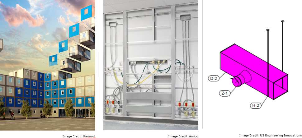
If we have a duct module with several intricate parts on the ends that made it really easy to assemble, it would make it extremely hard and expensive to manufacture. The point of DfMA is to consider both the manufacturing and assembly.
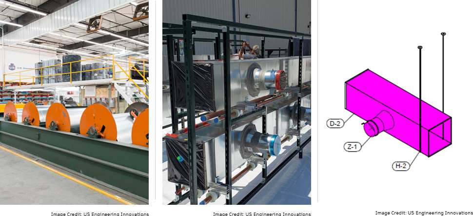
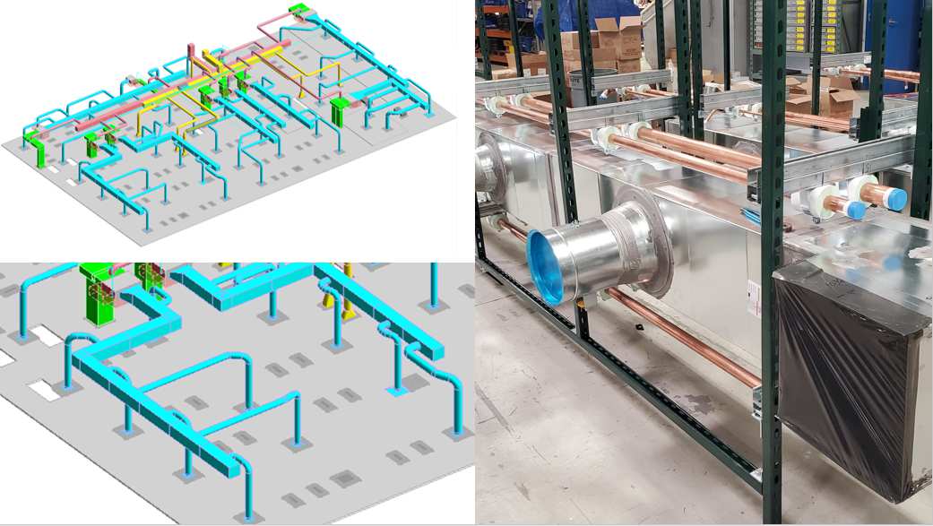
We took a module that was built for assembly and worked with US Engineering Innovations to refine what it looked like so that it was easier and faster to produce, but still easy to assemble and install in the field. That’s DfMA – the process of designing for manufacturing, as well as the assembly process.
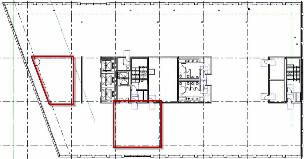
What do the following images have in common? You’ll see a retail store, a patient room, and an arena.
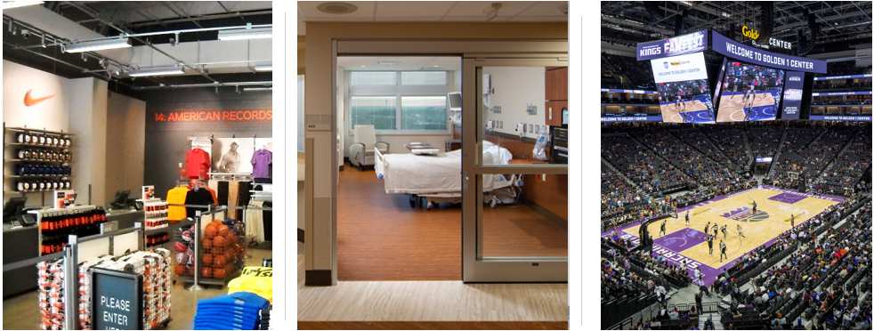
Their common thread is HVAC systems that contain low-volume ductwork where you could use a repeatable module as an installation, and it can be an air conveying method. Our approach was to use a repeatable component that’s easy to manufacture and that you could build up into an HVAC system for retail, something that serves a patient room, or something that serves a project as large as an arena.
A specific example of this was a recent project opportunity we had on a wellness clinic.
The project goals included modularizing as much of the design as possible in order to shorten the construction schedule and creating design solutions for different configurations that use the same components. The client was already investigating using modular components for assemblies for the walls, lighting, and power.
They hadn’t looked at the HVAC system yet, so we were able to identify this as an opportunity to apply DfMA – and we just happened to have a duct module we’d developed with US Engineering. The first step was to change our engineering mindset to orient around using the ductwork modules in our design.
We had to rethink not only ductwork routing but also our unit sizing and even our zoning. We ended up using the duct module for the main trunks of the air side system, reducing the number of unique components. The round duct runouts going to air terminals were all standardized to be the same size as well.
Another advantage of taking this approach was that we could standardize most of the unit sizes. This allowed us to go from having five or six different engineered units to two.
An important aspect of this concept is that design does not exclude the option of the traditional stick-build approach. This means that a contractor could take this exact set of construction documents and they could build it using the traditional methods or using the modular approach.
Applying DfMA Concepts
The basis of automation is standardization. By standardizing around a component, we are able to unlock more efficiencies and opportunities with BIM automation and generative design. It’s important to understand the parts/pieces that are actually installed in the field and how they impact the layout.
How do we apply those DfMA concepts to generative design? First let’s consider standard design. Standard design is an iterative process to identify options using set project constraints. This process is basically the same for anything you design. If you were designing a dog bed, you would still go through an iterative process to identify options around project constraints.
Generative design adds a computer in that process to rapidly identify all those options using set project constraints. So, it doesn’t identify all the options available. Instead it starts with given project constraints and outputs all the possible combinations within that framework. This allows the designer to explore those options faster than if you had done all the iterations by hand.
Generative Design = Computational Design + Optimization
Computational design and optimization are distinctly separate things, and you have to have both for generative design. Computational design, most commonly Dynamo, is also referred to as BIM automation.
Generative Design Success Story
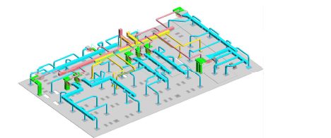
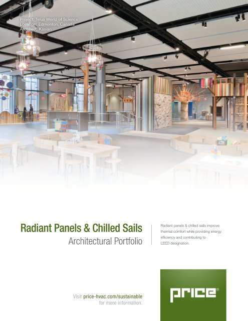
Here’s an example of generative design in MEP without using DfMA. This involves optimization and computational design. This seven-story building is a unique layout. The interior space design was also unique. It was open to structure and the architect wanted to use Price chilled sails as a ceiling plane/object. With the system type already selected, our goal was to maximize the load for the cooling offset. A secondary goal was to minimize the open space in the layout so aesthetically it looked as close to a ceiling as possible. The layout also had to fit into structural bays because the “ceiling” was to be recessed up in the bay.
In addition to that list, we of course had to consider cost. The key was to do so without doing full cost estimation. We also wanted to provide different options for aesthetics, because we knew that it was going to be a higher-end space. We wanted to present options, instead of just asking the team over and over as a guess and check scenario.
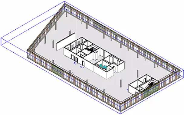
At Henderson we do all building systems design in-house, so we wanted to be able to coordinate our layout quickly with other disciplines, to make sure that the design wouldn’t conflict with other systems.
We had three different unit sizes (2’x4′, 4’x4′, and 2’x8′) to consider. The cost cooling offset power consumption was not a linear equation across all three options (a 2’x8′ was not just simply 2’x4′ doubled). We also had maintenance clearance and installation clearance considerations.
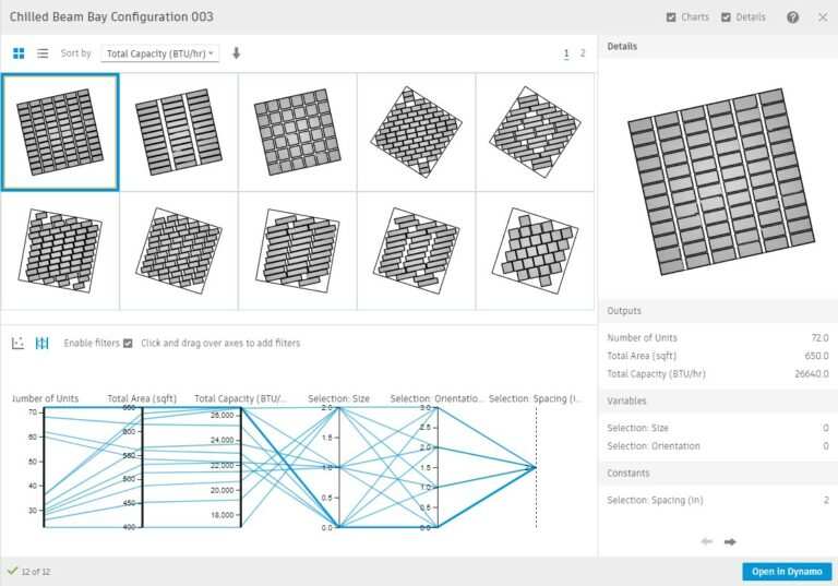
We targeted Autodesk Generative Design to iterate through each size of the panel on an array and then rotated that array on one-degree increments all the way up to 45 degrees. With a wide variety of options, we could sort by coverage area, cooling offset, and price.
Generative design allows you to pull elements from the Revit model using that as a foundation for computational design and optimization. Using these calculations, generative design can produce multiple design options, select one from a sort list, and populate those back in Revit.
In this example, we had square bays and non-square bays. Optimizing fitting a rectangle into a square bay is not that hard. However, whenever you apply that across all the other unique shape spaces and unit sizes, that’s where it became difficult. This is an example of sorting and selecting the final option, based on load which was the primary goal from the architect.
In the end, we were able to round trip the selection back into Revit with real mechanical systems. We placed them into design options for layout in the architect’s model before we committed to them.
Including DfMA
Now that we’ve shown an example of generative design in the MEP world, we’re going to apply DfMA (our duct module) to generative design.
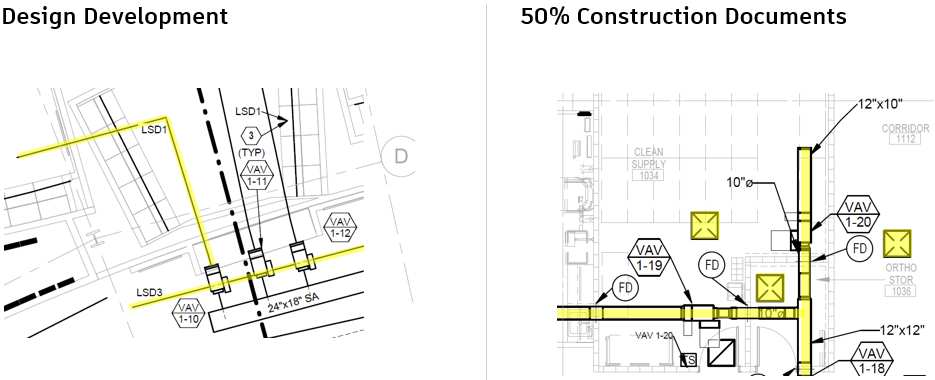
This is how our design progresses naturally. Below you can see the difference between the main duct runs laid out in Design Development (DD) and 50% Construction Documents (CD). Notice that the equipment, terminals, and the duct all change between different milestones. We intentionally design this way to be as flexible as possible for as long as possible. That way, it’s not always a last-minute rush and allows for easier adjustment if/when things change.
There’s an innate emotional element to design. You have an emotional investment in the time and energy you spent putting that design together. If something changes, it can feel as if it’s a personal attack on your design when really they just needed to add another wall.
We wanted to take that emotional component out of the design and be able to redesign accurately and very quickly, while still maintaining our design workflow.
This is where we tried generative design and failed because we were looking at the wrong problem or the wrong tool. We tried to automate this entire milestone deliverable. We tried to optimize terminal, duct main, and unit placement. All of those components have an interaction with each other and the math became simply too complicated.
Our design steps change based on the design phase. What we were really looking for was an easy button to go from milestone to milestone, so we could still be as flexible as possible for as long as possible. However, there simply is no easy button for 100% CD layout.
Generative design is best used for a single design step to be able to automate that layout and optimize the calculation. We backed up a bit and looked at our design process and we decided to focus on moving from 50% CDs to 100% CDs. You can see the difference in the layouts below.
Our backup plan was straight-up BIM automation since we really don’t need computational design and optimization to say “this is the nearest point on the main where this terminal can connect to.” We wrote BIM automation through Dynamo to make those connections. What that left us with was a problem statement, and that we could automate. Problem statements are very important.
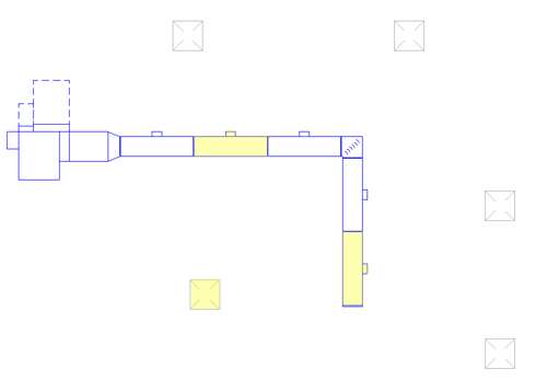
The problem statement here is, “place the duct module on the main line of the identified duct and connect the terminal into that module.” The duct was replaced as the components were placed because the module was actually a ducting fitting that was 5’ wide.
Here’s an easy example of that:
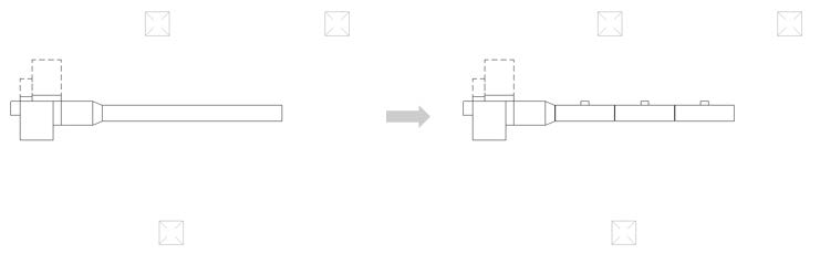
The easy part here is that our duct happened to be 15 feet long our duct modules were 5 feet. Since we have three modules and three terminals, the math is easy.
The important part here is that you don’t have to create a module and work with contractors to create new things, you just simply have to understand what the components are you’re applying in the field. If your components are 10 feet long, design in 10-foot increments. Traditionally, we would simply just lay out mains in the general length and location.
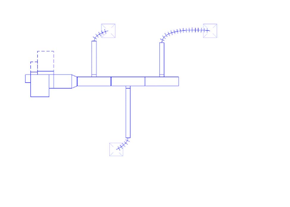
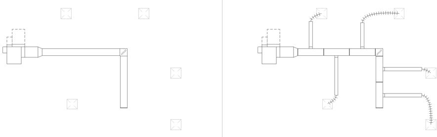
In this scenario, we have three modules and three terminals. We are able to automate connecting those together. That layout becomes more difficult whenever you go around a corner. You wouldn’t think this is that hard, but from a programming standpoint, it becomes increasingly complex.
We replaced our mains with our modules just like we’ve done before. However, the math isn’t so simple because the terminal on the lower left is equidistant between the two highlighted modules. It’s a tie for which one to connect to via automation.
However, whenever you look at it in context of the entire design from a human eye, you’re able to see that this module is most logically connected to this last terminal on the right. Therefore, the lower left terminal connects most logically to the center, upper module. That’s where the human decisions come in. It’s not always easy math.
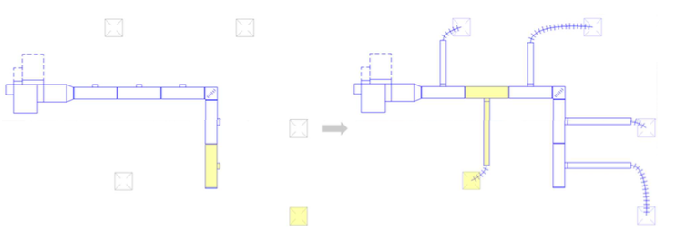
Where it becomes hard is whenever you actually have more terminals than you have modules. In this scenario, we added another terminal because of design requirements and we only had so much room to run our main line of our ductwork. The simple solution there is you just add another module. But since we live in the real world we found that our modules were still too big. We needed smaller pieces!
Instead of a 5′ design, we also created a 2.5′ design in conjunction with US Engineering. This allows us to make more granular changes and fit into the smaller spaces than we would be with just a 5’ module.
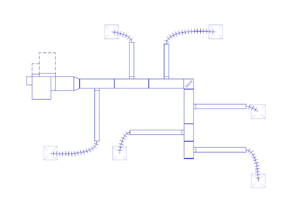
We lay out ducts based on the location, size of our terminal, and airflow. This is standard practice for engineering. What’s not standard is going back and modifying the duct to be optimized for assembly and manufacturing.
With a little bit of effort, we can set our designs up for success. We used BIM automation to replace the last 5′ module with two 2.5′ modules. We split out the connection into a final step as well, so they are scripts that run back-to-back. Instead of making them one giant script, we allowed humans to be involved in the process and make decisions. They can visually see how many terminals and modules they have and make educated decisions instead of having the machine do it for them.
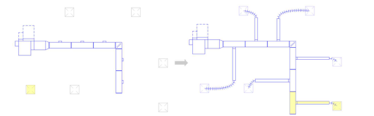
Back to our previous layout, instead of just replacing the last 5’ module with two 2.5′, it becomes an issue of which is the best module to replace. What happens if I replace the first module and align with two 2.5′ instead of the last module?
The last module was our target simply because we had already connected all the other modules – that’s where the emotional part of the design comes in. If I have already done all this work, then I’m not going to go back and redesign it because I may think I have a better answer. Our problem statement becomes “iterate replacing each module with smaller modules and optimize the duct length.” Optimizing the entire duct length is what we’re after. That overall includes the mains and the runouts added together.
For this we would use generative design, because we have a computational design problem and an optimization problem. We have our mains/terminals placed and there’s the magenta designation for the two 2.5′ modules. You can see that moving throughout the design and then it automatically connects to the nearest one to calculate.
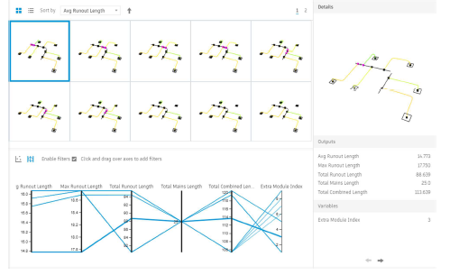
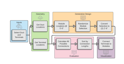
Below is the rough outline of the generative design process that includes getting objects, which provide the inputs and geometry, and feeding them through the generative design algorithm and evaluation stages, finally presenting them through the generative design interface for design visualization and analysis. This is the process that we use to develop our code.
Sorting by overall duct length, we can iterate through a couple of the options and decide which one is our best of total combined length. Some are very close and that is where the engineering judgement comes in. This helped us decide that the first module in that line was the best one that would give us the optimized length.
It’s actually really hard to roundtrip that decision back into Revit so we ended up just getting it back to the BIM automation instead of relying on generative design to try to connect all those systems. Revit systems can be very finicky to reconnect all those connectors. We ended up using generative design to find the solution and then relied on the human to actually implement that design, giving them complete control over the design process.
Want more? Download the full class handout to continue reading.
Adam Roth works as a BIM manager for Henderson Engineers Inc., based in Lenexa, KS, with 700 employees in 13 offices nationwide. He oversees and provides training, support, and implementation for the firm’s two primary design software packages, Autodesk Revit and Autodesk AutoCAD. He has 11 years of experience with four of those focused on electrical design for commercial retail. Additionally, he is a Revit Architecture Certified Professional as well as a Revit MEP Certified Professional. Adam is heavily involved in the Revit development and documentation of standards for the firm. He also provides monthly presentations and demonstrations to users regarding new developments, workflows, and techniques.
Sean Turner is the innovation director at Henderson Engineers, where he represents innovation to clients and partners and manages internal innovation projects. He thrives on finding new ways to approach building systems design to provide high-performance, optimized projects while also making the process more efficient and engaging for the project team.

Jared Carlson, engineering director, will be presenting Navigating Change when Introducing New Tools and Processes to Maintain Buy-In and Insure Adoption at the Advancing Design Quality Management Summit. He’s excited to dive into the innovative ...
Read More
Starting May 13th Mark Chrisman and Laura Longoria will be in Orlando for BOMA International’s Medical Real Estate Conference. Team Henderson is excited to explore healthcare real estate from every angle and lean into what ...
Read MoreJoin our email list to get the latest design innovations, technical content, new projects, and research from Henderson’s experts delivered straight to your inbox.